|
Module 16-1 |
Updated: 07/05/2005 |
|
Maintaining Video Quality Part I
Although today's video equipment includes automatic circuitry to adjust audio and video levels, these automatic controls are programmed to maintain only rudimentary technical parameters, which may or may not be in line with your desired results. Thus, if you are to consider yourself "a pro," (i.e., a professional who can produce consistently good results) it's essential that you understand the elements in this module. In monitoring and controlling picture quality two pieces of equipment are essential.
Although these are generally separate instruments, in some cases both can be displayed on a single TV monitor or on the screen of a computer-based editing system. In this module we'll cover some of the most basic elements of the waveform monitor and vectorscopethose that any professional videographer should knowand we'll stay away from their technical dimensions. |

|
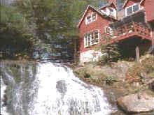
In critical professional video work waveform monitors are used as scenes are being taped. During editing, they are used to monitor and maintain video quality and scene-to-scene consistency. By looping the video signal from a camera through a waveform
monitor, the output of the camera can be electronically graphed as shown on the
right. The photograph on the left contains tonal values from full black to bright white. It will give you a normal waveform pattern such as the one shown above. The dark areas of the video picture are represented near the bottom of the waveform scale (marked "black level" above), and white areas appear at the top (marked "white level"). A scale along the side of the waveform monitor starts at about -40 (at the very bottom) and goes to about +120 (at the very top). The numbers on the waveform monitor are based on IRE units, units first established by the Institute of Radio Engineers. Ideally, video levels (for an average picture) should be somewhat evenly distributed between 7.5 (where "black" should start) and 100 (where "white" should end) just as it's illustrated in the waveform above.
Ideally, with a properly adjusted computer monitor (set to 256 colors or more), you should see 16 divisions in this gray scale. Good computer monitors can reproduce colors and gray scale divisions far beyond what's shown above, and with greater accuracy than standard TV sets. Waveform monitors, together with light meters (to be discussed in the modules on lighting), are your primary tools in ensuring proper camera exposure and good video quality. In this regard, it's helpful to know that one f-stop in a light meter translates into 20 IRE units on a waveform monitor. In TV, as in life, things are not always the way they are supposed to be, so now let's look at some problem areas. Camera underexposure
(insufficient light on the target) results in low video levels. On a waveform monitor
this is immediately obvious, since the peak video level may only come up to 50 or
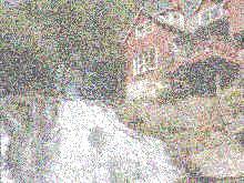
so on the waveform monitor scale. This can normally be fixed by If video is initially left at a low level and then raised or boosted later in the video recording or transmission process, the resulting picture may look grainy because of video noise, as shown (in somewhat exaggerated form) here.
On a waveform monitor the result would be similar to what you
see on the right. (Although two identical fields are
typically displayed on a waveform monitor, to simplify things we'll show just one
in the remaining waveform drawings.) On the gray scale below you can also
see the loss of detail in the white areas.
In Part II of this module we'll look at the issue that causes the most problems for video quality.
(Click on "more" for the second half of this section.) |
 opening up the lens iris one or more f-stops.
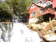 If
the target of the camera is significantly overexposed (too
much light), the waveform monitor will show a video signal significantly above 100.
Left uncorrected, this will cause significant distortion in the video picture.
If
the target of the camera is significantly overexposed (too
much light), the waveform monitor will show a video signal significantly above 100.
Left uncorrected, this will cause significant distortion in the video picture. Under
these conditions some camera circuits clip off the white level as shown above. Note
that detail has been lost in the white areas.
Under
these conditions some camera circuits clip off the white level as shown above. Note
that detail has been lost in the white areas. Another
problem is compressed blacks. The resulting video will be dark, without any
detail in the dark areas. A gray scale would show a loss of separation between the
divisions at the lower end (right side) of the scale, as shown below.
Another
problem is compressed blacks. The resulting video will be dark, without any
detail in the dark areas. A gray scale would show a loss of separation between the
divisions at the lower end (right side) of the scale, as shown below.