|
Module 16-2 |
Updated: 07/05/2005 |
|
Maintaining Part II
A final concern and one that results in poor video quality is caused by subject matter that exceeds the brightness range capabilities of camcorders. A video camera is only capable of reproducing a limited range of brightness-something you have to constantly keep in mind when bright lights, windows, white walls, etc., appear in a scene. A range in brightness that exceeds about 30:1 (with some major picture elements 30 times brighter than others) will cause problems. Rather than "clip off" the offending areas with a resulting loss of detail in the light areas of the picture (as shown earlier), many video circuits will automatically bring down the entire video level so that it will all fit into the standard (limited) range.
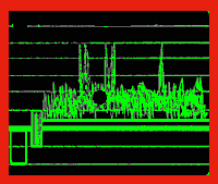
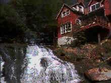
Note in the waveform above that all the video is within the 7.5 to 100 range, but that "spikes" (caused by light reflections from the waterfall) take up more than half of the range. As a result, the rest of the video ends up in a small (and rather restricted) area. In the photo on the right above that the middle-to-dark range of the video is compressed into a small area. The result: a dark picture. If a person were standing in this picture, their skin tones would be much darker than normal.
The problem of
exceeding the brightness range of the video system (and a resulting compression
of the gray scale) is one that you often see in amateur videos. Note that in the photo on the left the brightness range of this scene greatly exceeds the capability of the video system. This is caused primarily by the bright sky in the background. The automatic exposure camera setting that was relied upon results in a complete loss of detail in the horse.
Can you have it both ways? Possibly, at least on some professional cameras. A knowledgeable engineer may be able to adjust the brightness response curve of the camera to bring the bright areas into the basic picture. However, doing so, will distort the gray scale, which may objectionably distort the rendering of the other subject matter. As we will see when we look at the subject of lighting, adding light to dark areas, or darkening down the bright areas, represent better approaches to solving this problem. Most automatic cameras - like the ones that gave us the "black" horse above with no detail - give you the option of turning off automatic exposure and adjusting the iris manually. If you can't do that, remember that the camera's backlight control will provide you with some control in scenes that have bright subject matter, such as windows or bright backgrounds. Even someone wearing a white or yellow shirt will often cause problems.
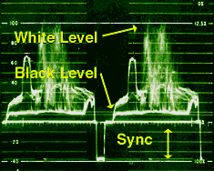
In this "blacker-than-black" area there are some important timing signals referred to as sync, a term that is short for synchronizing pulses. These are the high-speed timing pulses that keep all video equipment "in lock step" during the process of scanning lines, fields, and frames. These pulses dictate the precise point where the electronic beam starts and stops while scanning each line, field, and frame. In fact, without these timing pulses, electronic chaos would instantly break out between pieces of video equipment. A single source of sync from an electronic device called a sync generator is used to supply a common timing pulse for all equipment that must work in unity within a production facility.
Too much sync and the black level of the video will be pushed too high (graying out the picture); too little and the black level will cut into the sync, and the picture will roll and break up. We've noted that full-range video extends from 7.5 (the darkest black) to 100 (maximum white) and that sync goes from 0 to -30. That leaves the 0 to 7.5 range shown above between the bright lines about two-thirds down from the top of the illustration. That's an important one too. This represents the blanking signal (sometimes called pedestal or setup). Adjusting this affects not only blanking (which blanks out the electron beam as it returns after scanning each line and field), but also the overall black level of the video. There's a knob on the camera control unit, or, if you are working with a computer editing program, on a sliding control marked "blanking," "pedestal," or "setup," that controls the level of the blanking signal. To keep from
getting too technical, we've sidestepped an issue here that has implications for
TV graphics.
|
|
Vectorscope The eye sees color very subjectively,
so when it comes to making accurate judgments about color, our eyes can be easily
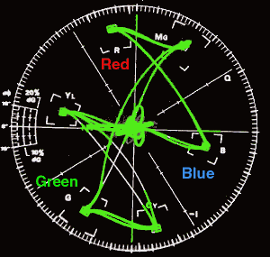
fooled. The device that does this is called a vectorscope and it's commonly seen in TV control rooms and as part of computer editing systems. We'll skip the technical stuff involved in this, and just concentrate on six little boxes marked R, G, B, Mg, Cy and Yl on the face of the vectorscope. As you might suspect, these stand for red, green, blue, magenta, cyan and yellow, the primary and secondary colors used in color TV. When a camera or any piece
of video equipment is reproducing color bars, (shown below on the right) the primary
(red, green and blue) and secondary (magenta, cyan and yellow) colors should appear
in Without a vectorscope, you can often balance the colors fairly accurately by simply making sure the yellow bar is really yellow. Often by adjusting yellow correctly the other colors will fall into place. But sometimes things aren't that simple. If primary or secondary color bars wander significantly out of their assigned vectorscope areas, there are problems. Sometimes things are easy to fix (like a simple, twist of the phase adjustment knob); sometimes they're not, and you will have to call in an engineer. In addition to hues (colors), the vectorscope also shows the amplitude or saturation (purity) of each color. Color saturation, which is measured in percentages, is indicated by how far out from the center of the circle the color is displayed. The further out, the more saturated (pure) the color is. Since professional nonlinear editing systems (to be covered later) have both vectorscopes and waveform monitor screens that can be displayed, you can keep a constant eye on quality and make scene-to-scene adjustments as necessary. This is the only way that you will be able to consistently and unobtrusively cut a variety of scenes together during the editing phase. Of course all
of these quality measures have to be displayed accurately on a TV monitor in order
to be verified, so it's important to be able to trust your video monitor. The zone system that many Directors
of Photography and professional still photographers use to insure accurate tonal
renditions can also be applied to video production. This is discussed
|


 Although this example represents extremely difficult subject matter-a situation
that would be best avoided, if at all possible-note on the right how the picture
can at least be improved significantly when the camera's iris is manually opened
up three or more f-stops. (Of course detail in the sky disappears, but we'll assume
you are more interested in the horse.)
 On a waveform monitor the bottom line in the sync
should be at -40 (the very bottom of the waveform scale) and the top should extend
to the baseline, or the 0 point on the scale.
 Thus,
we need a reliable way of judging the accuracy of color, as well as for setting
up our equipment to accurately reproduce colors.
 their marked boxes on a vectorscope.